![[IMG]](https://photos.smugmug.com/Motorcycles/2019-GPX-TSE250/Odd-Deets/i-zFqvX2r/0/a1fdd1e9/XL/IMG_20181025_220326-XL.jpg "Click this image to show the full-size version.")
Race ECU on the Left – OEM on the Right.
While swapping ECU’s I noticed a bit of an issue.![[IMG]](https://photos.smugmug.com/Motorcycles/2019-GPX-TSE250/Odd-Deets/i-RqVDt7c/0/8d5f005b/XL/IMG_20181026_072740-XL.jpg "Click this image to show the full-size version.")
Yup, it seems I managed to crack the right side subframe. No idea how. No idea when.
I suppose this winter I’ll strip it all down and see what I can do. A sharp eye may also note that I no longer have the original self tapping screw holding the CDI down. Why might you ask? Well upon replacing, the plastic completely stripped out where it threads in. Further inspection revealed that the CDI was threaded into 2 very thin areas. Odd, as literally a couple MM away, are 2 hefty self tapping screw holes with solid bosses beneath them. Why these were not used? I don’t know 100%, but it appears the CDI was relocated nearer the fuel tank in order to allow room for the starter solenoid. When I have more time, I’ll investigate further, but I needed to do something to at least hold the CDI in place for the upcoming dual sport.
So since my OEM rear fender broke (right side lower retaining screw, above the exhaust), I ordered a proper Acerbis one, and the difference is night and day. The plastic is more supple, I assume they use either a toughened PP or something added to it to allow a bit more flex\give than the one that came stock. In addition to that, a sharp eye will note that the Acerbis fender has 2 aluminum washer\spacers molded into the fender. The OEM TSE unit did not, and IMO is partly why the fender failed multiple times on me.![[IMG]](https://photos.smugmug.com/Motorcycles/2019-GPX-TSE250/Odd-Deets/i-j62fMN6/0/6a25de12/XL/IMG_20181026_072805-XL.jpg "Click this image to show the full-size version.")
You may also note that the screw on the top right is not 100% flush. As I was tightening this, the threaded insert in the subframe stripped out on me. I’ll have to work on extracting this later and fix this issue.
The following picture shows how I had to fix the stripped out threaded inserts in the sub-frame. I may look at replacing these with better threaded inserts (we use a LOT of them at our shop that are molded into many various products), but for now, the most straight forward option was the following:![[IMG]](https://photos.smugmug.com/Motorcycles/2019-GPX-TSE250/Odd-Deets/i-fTdK9sm/0/2a855fd4/XL/IMG_20181026_072800-XL.jpg "Click this image to show the full-size version.")
![[IMG]](https://photos.smugmug.com/Motorcycles/2019-GPX-TSE250/Odd-Deets/i-CPz3fL4/0/dd0f14c8/XL/IMG_20181026_072809-XL.jpg "Click this image to show the full-size version.")
It’s ugly, a bit of a PITA to deal with, but it holds the fender on. So there’s that.
There were some positives, and I did not get any pictures of the engine reassembly. Hands were oily and I didn’t want to muck up my phone.
The new shifter went in smoothly, and once the side cover was on, the difference was immediately noticeable. I had 0 left to right play (grabbing shifter on left side of engine, and push\pull it in\out). It would not move. My old one would shift back and forth quite a bit. My guess is that the original moved too much, allowing the pawl the slip on the star, which then allowed the pawl spring retainer to collide with something and shear itself. It’s my opinion that nothing on the pawl side is what is the “full stop” for the shifter. That is 100% decided by the tangs on the left of the shifter by the main shifter return spring. I failed to get a measurement to compare with original, but a small visual check appeared to have a more narrow gap than my original unit. Whether this was wear, damage, or a dimensional issue from manufacturing, I do not know.
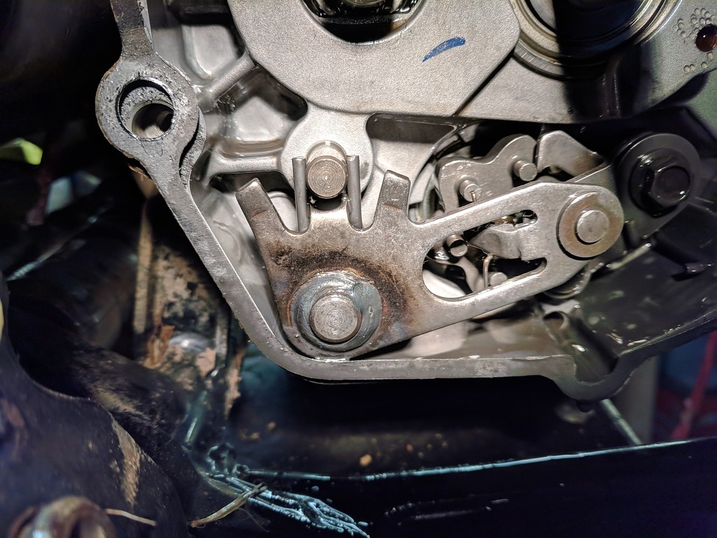
The next thing that popped up to me during reassembly was with regards to the oil pump. Since the lines were pulled, I wanted to get everything bleed correctly. I opened up the DT230 manual and began reviewing. Upon review, I noted the following:
To note here, at 100% throttle, the notch (A) should align with the output (B). No matter how much I adjusted the cable, I could not achieve this setting. Has anyone else seen this? I assume since its got a heft amount of hours, it must not be super critical here, but I adjusted as much as I could to get as close to max as possible.
Well, that’s about it for now. GPX did ship a little extra for me, so that was nice. Thanks for the swag & pardon the sweatshirt.
![[IMG]](https://photos.smugmug.com/Motorcycles/2019-GPX-TSE250/Odd-Deets/i-4r4qtjC/0/949242a0/XL/IMG_20181025_174957-XL.jpg "Click this image to show the full-size version.")
And kudos for it not being a flatbill